
Introduction
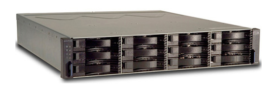
I recently picked up a used IBM TotalStorage DS3400 storage array. The 3400 was part of the IBM TotalStorage DS3000 series of entry level storage systems, of which there were three models in total – the 3200 which was SAS only, the 3300 was iSCSI + SAS, and the 3400 was FC + SAS. The product line was announced in 2008 and went end of life in 2016. Beyond the host server connection, the models were otherwise identical.
They all sport 12x 3.5″ SAS/SATA disk bays at 3Gbps, dual controllers, and dual power supplies, all in a 2U chassis. They could, in theory, have up to four additional ‘EXP3000’ expansion arrays, each with an additional 12 disk bays, providing up to 48 disk bays in total.
Mine came equipped with 6x 1TB SATA 7.2k disks, dual 4GB FC controllers with 512MB of cache, and dual power supplies.
I picked up this particular unit because I wanted to do some IBM PowerHA testing in my AIX home lab, and the 3400 is on IBM’s PowerHA Hardware Support Matrix, where my current DS3512 is not.
Unfortunately, the IBM PowerHA Hardware Support Matrix doesn’t appear to have been updated since 2015 (this article was written in June of 2021) and there are many dead links. Several spots where I suspect it would say other models of hardware, there are just ‘FLASH#####’ links that go to dead pages. I can’t be sure if some of these links are for other model-numbers, one of which may actually correspond to my DS3512. However, in doing some research for this project, I was able to find only one reference for using the DS3500 series storage array with PowerHA, and it was for PowerHA v6.1 for AIX v6.1, both of which are pretty old at this point.
Conversely, I still see reference to the DS3400 series in some of the more modern PowerHA/AIX 7.1 documentation, so that’s promising. We’ll find out when we get there I suppose.
For purposes of my PowerHA testing and my home lab in general, the differences between the 3400 and the 3512 are negligible, mostly disk and FC connection speeds. The 4Gbit 3400 will run just fine on my lab’s 8Gbit FC network. In this case, I needed 8Gbit technology as it is a requirement for NPIV, which in turn is a requirement for LPARs to get direct FC storage through VIO, which in turn makes managing my lab significantly easier. And honestly, that’s the ‘modern’ way to do things.
Regardless of whether or not this project succeeds, I was able to get the 3400 for a very reasonable price. And since it is used, no connection information was provided with the system, IP addresses and passwords for the controllers were unknown. So, since I didn’t know any of these things, and I didn’t care about the previous configuration nor data, a full system reset, or factory reset, was in order!
What IBM calls ‘IP Management (Out-of-Band)’ is my preferred method for configuring and controlling these kinds of arrays. It uses a piece of IBM software and the controller’s onboard ethernet controller for management of the array, and is something I’m fairly familiar with. While I believe it is technically possible to manage the array via direct connection (In-Band) through SAS or FC, but I’ve never really gone down that road, so I’m not sure if it would actually work for zoning LUNs to hosts and whathaveyou. Since ‘in-band’ management wasn’t an option, that left two paths to manage the array, either figure out the network settings by trial and error, or find a serial cable to connect to the controllers.
Since I didn’t immediately have a serial cable that would work on the controllers, I first tried to discover the existing IP addresses. In theory this could be done by watching the controller network traffic and then determining the original IP addresses. So I connected both controllers directly to a small 10/100 switch, and then to my Linux laptop, configured to watch the network traffic via WireShark. Sadly that didn’t work. I never saw any traffic that would indicate the controllers’ IP addresses, nor even what subnet they may have been configured for. However, I suspect that I may have simply not been using WireShark correctly. I also attempted to do a ping search for the controllers via nmap on the same laptop. However, again I was unsuccessful, as scanning what I assumed were somewhat likely and reasonable IP ranges (192.168.xxx.xxx, 10.xxx.xxx.xxx) never yielded any results, even after running for a few days.
Since it was taking such a long time, and I wasn’t sure I was going to get a good result based on my previous experiences with WireShark, I decided it was time to try out the last connection option, the serial connection.
On a side note, I also found that the system is based on the LSI Engenio system, which while interesting, never got me any additional information. Apparently it was a widely ‘rebadged’ storage platform, that IBM, SUN, NetAPP, and others resold.
Here are some links to sites that helped me:
http://odme.blogspot.com/2007/05/today-i-had-to-configure-ds4300.html
https://absoblivion.wordpress.com/2011/12/31/recovering-lost-password-for-ibm-ds3400/
http://user-techdocs.blogspot.com/2010/03/how-to-connect-to-ds4000-system-using.html?m=1
Serial Cable
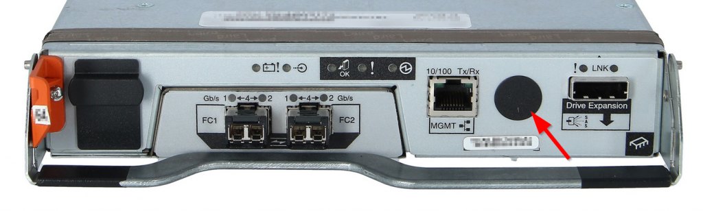
The serial cable. Both controllers have unlabeled serial ports on the back, often hidden behind small round black stickers, and use a mini-DIN connector with the same pin orientation (but obviously not connection) as a PS/2 keyboard. Since this is such an unusual cable, I didn’t have one in my collection.
The IBM provided serial cable, P/N 13N1932, converted the mini-DIN connector to a normal female DB9 serial connector. However, at least in 2021, this cable is unobtainable for a reasonable price. Several vendors online claim to have the cable available for purchase, but for absurd prices, assuming they genuinely have it available at all. Such high prices were simply not options for me, as I paid less for the entire array than the prices of some of these cables. There do appear to be several international vendors on eBay selling “NEW For DS3000 DS3200 DS3300 DS3400 IBM 3M Storage Control Line #H103F YD” cables, but again for relatively high prices.
Examining pictures of the cable, it looked like a very simple cable, most likely with no active electronics within (for example, level-shifting 3.3V logic to 5V, which is sometimes necessary) so making a cable would probably be the easiest and cheapest way forward.
Luckily, I was able to locate a pinout of the cable here, which claimed to have gotten the pinout from a Russian website, but I have been unable to locate.
Again, luckily, the pinout given on that website was the pinout that worked for me.
| DIN | DB9 | FUNC |
|---|---|---|
| 1 | 3 | TX |
| 2 | 2 | RX |
| 3 | 5 | GND |
| 4 | 4 | DTR |
| 5 | 5 | GND |
| 6 | N/C | N/C |
| SHEILD | SHIELD | SHIELD |
Note to self – is it possible to use one of the old Logitech PS/2 to Serial mouse adapters from long ago, or are the pinouts different?
I was able to locate an old Belkin PS/2 keyboard extension to use as a donor PS/2 male cable, and I used these “Connector DB9 RS232 D-SUB Serial Adapters” connectors sourced from Amazon. I clipped off the female end of the Belkin cable, stripped back the jacket, crimped ferrules onto the tiny wires, and connected them to the DB9 connector.
Regarding the DB9 connectors, I don’t believe I would recommend those exact ones, but I love the idea of them. They are relatively expensive per-unit, and relatively large. However, they are extremely convenient, and do make assembling the cable easy. There was one strange thing, however. The long screws that go through the body of the connector and would normally hold the adapter to your PC or whathaveyou, are threaded too long. Meaning, that you have to screw them through the threads on the connector itself, and then into the connector on your PC, but they would remain threaded into the DB9 connecter as well as threaded into the PC’s connector, making for an uneven mechanical connection. Normally such screws are of the ‘captive’ style, these are clearly not. It rather looks like whoever made this connector was told about them, but had never actually seen or used one before. Regardless of the minor issues with the mechanical design of the adapter, electrically it worked just fine.
Anyway, I now have a serial cable! Let’s try it out!
Note – The cable is apparently able to support several generations of DS array, the DS3200, DS3300, DS3400, and the EXP3000. I have also independently verified that it will also work on the DS3512. Presumably the cable will also work for the other re-branded versions of the LSI controller.
Note 2 – The DS4000 series arrays have many things in common with the DS3000 series, as the 4000’s serial cable has the 39M5942 part number, and appears to be similar if not identical to the cable used here.
Serial Console
Naturally, to use the serial connection on the array controller, it is necessary to use a serial console. I elected to use my trusty Linux laptop and the PuTTY software, as that is what I’m most familiar with. Any number of other programs could be used, like ‘screen’ or ‘cu’, or ‘minicom’. For the serial connection itself, as my laptop doesn’t have an onboard USB connector, I used an ancient Belkin USB–>Serial adapter I have had laying around and it worked great.
So long as you can get a serial console hooked to that DB9 connector, it’ll work. Bust out an old VT220 if you need to.
A null-modem adapter was NOT needed. Theoretically, if you needed a null-modem adapter, it should be as simple as switching around the TX and RX pins in the cable you just made to eliminate its need.
Connect the cable to the serial port of either controller. I recommend starting with the A controller, which is usually on the left-hand side of the array, if you are looking at it from the back.
The connection settings that worked for me was 38400,8,n,1. Near as I can tell, it is possible to use any speed as the controller will auto-sense the speed, but 38400 is what worked for me. When I had the speed wrong, I would get gibberish on the screen.
Once you have it connected at the right speed, pressing the <ENTER> key should display a blank carriage return on the screen. This generally means that everything is working. If you just get gibberish, then change your port speed, and try again. Note that no prompt or text will be displayed due to keyboard input, but you should see system events scrolling past if system conditions change, such as unplugging the other controller, unplugging an ethernet cable, etc.
Serial Console Login Prompt
Getting the CLI login prompt was tricky. Near as I can tell, there are two ways to get the login prompt, and the method depends on the array controller firmware version. I’ll start with the one more commonly documented on the internet first, then the one that worked for me.
Method 1
- Connect serial cable between your terminal and one controller of the array.
- Initiate serial connection.
- Send BREAK signal by pressing <CTRL>+<BREAK> and you should get a message similar to this:
"Press <space> for baud rate within 5 seconds".
- Press the <SPACE> key within 5 seconds and the baud rate gets set to the baud rate of your connection.
- Send the BREAK signal a second time and you get this:
"Press within 5 seconds: <esc> for SHELL, <break> for baud rate."
- Press the <ESC> key and get the login prompt for the shell.
Method 2
- Connect serial cable between your terminal and one controller of the array.
- Initiate serial connection.
- Send BREAK signal the first time by pressing <CTRL>+<BREAK>.
- This message will display:
"Press within 5 seconds: <S> for Service Interface, <BREAK> for baud rate"
- Send BREAK signal a second time by pressing <CTRL>+<BREAK>.
- This message will display:
"Set baud rate: press <space> within 5 seconds"
- Press the <SPACE> key within 5 seconds and the baud rate gets set to the baud rate of your connection. This message will display:
"Baud rate set to 38400"
- Send BREAK signal a third time by pressing <CTRL>+<BREAK>.
- This message will display:
"Press within 5 seconds: <S> for Service Interface, <BREAK> for baud rate"
- Send the escape signal by pressing the <ESC> key.
- Note, the ESC option still exists, it is just hidden and not displayed!
- The VxWorks login prompt will display.
Note that the ‘Service Interface’ and the ‘Shell Login’ are two very different things. We want the shell login, and for the purposes of this process, we don’t use the service interface. I have yet to discover any IBM Service Interface password, nor any IBM documentation that would indicate its use. Albeit I have not looked very hard. There is a documented SUN usage of the command, however, but following those steps on my IBM array didn’t work, go figure.
VxWorks Login
Now that we have a login prompt, we need to log into the array. Thankfully there is a default, serial-console only, login that can’t be changed. However, it seems that there are a few different password combinations out on the internet. I’ve collected as many of them that I could here.
The login username is always ‘shellUsr’ and the password can be any of these:
infinitiwy3oo&w4y2llojpkra16wenpassword
According to some anecdotes online, the ‘infiniti’ password is hard-coded and cannot be changed. However, that password is not the one that worked for me, it was the ‘wy3oo&w4’ password. Again, this may be due to differences in firmware versions over time.
Serial Console GUI Password Clear
Now that we have been able to log into VxWorks, the first thing we want to do is clear the existing GUI management password. Note, however, that this is not a ‘configuration reset’ or ‘factory reset’, we are simply resetting the GUI password, so any customizations made by the previous owner will still be in place. Honestly, however, that won’t matter much.
- Log in, and you will be presented with the VxWorks prompt:
->
                        Serial Port shell started.
->
- Clear the password with the following command:
isp clearSYMbolPassword
- It will return with something like this:
value = 61495536 = 61495536 0x3aa58f0
I’m not sure if those values would be different on different arrays, but they were the same on both controllers on mine.
Now the GUI password has been reset to blank. We’re half-way done!
Serial Console Network Config
Now that we have the password cleared, we need to configure the network interface.
- Again, once logged in to VxWorks, run the following command to see the current network config:
netCfgShow
- While interesting, ultimately it is more than likely wrong for your situation, so we will need to reset these settings.
- Use the following command to set the network settings as appropriate for your network:
netCfgSet
- Once complete, use the following command to log out and exit:
exit
Repeat for 2nd Controller & Confirm Networking
Repeat these configuration changes for the second controller, as technically you have only changed the configuration on one of the two controllers. Ensure that now both controllers can be pinged via their network interfaces. I could now telnet to both IP addresses and login using the same ‘shellUsr’ account. However, it may not be possible to telnet to the controller if that option has been disabled.
GUI Connection
Now that we have both controllers configured with reset passwords and properly configured networking, we still need to be able to manage the array. This is done via the IBM DS Storage Manager software. I’m working with version 11.20 of the software.
This software can be somewhat difficult to locate, but can be found in the usual places. I believe it can be run on a variety of operating systems, but I’m running mine on Windows.
- Open the software.
- Click the ‘Add storage subsystem to view’ button.
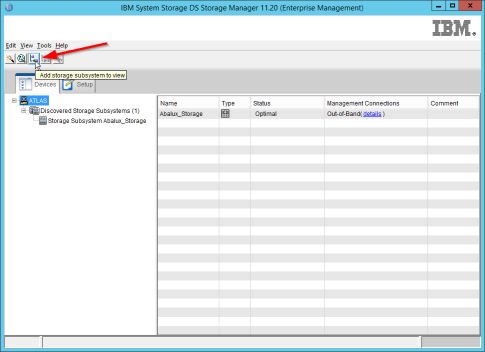
- The ‘Add New Storage Subsystem – Manual’ window will appear.
- Enter the 2x IP addresses of the array in the two controller fields, and then click the ‘Add’ button.
- The ‘Storage Subsystem Added’ window will appear.
- Click the ‘No’ button.
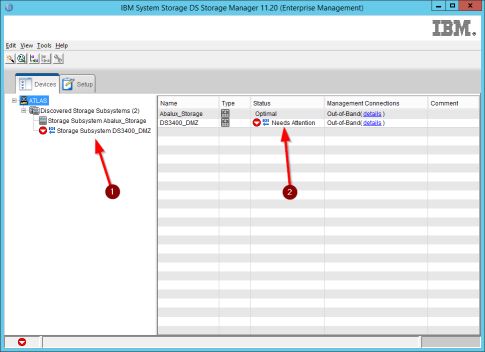
- The new array will appear under the ‘Discovered Storage Subsystems’ dropdown.
Note, the array will likely display a strange name from the previous owner’s configuration, and that it needs attention.
GUI Login
Now that we have the array configured within the management software, we have to connect to the array to start managing it.
- Double-click on the array shown in the list.
- The Subsystem Management window will appear.
- If the ‘Synchronize Controller Clocks’ window appears, click the ‘Synchronize’ button to sync the clocks to the management workstation.
- If the ‘Initial Setup’ window appears, click the ‘Do not show…’ checkbox, and then click Close.
- The main configuration screen will now be displayed.
Complete!
At this point, the configuration is complete! Everything else about the array can be configured through the GUI software, which I will leave as an exercise to the reader.
Best of luck!