
Author’s Note – let me begin this article by saying that I am not an electrician. I’m not an expert. I don’t recommend that anyone take what I have said here as instruction, advice, recommendation, or even truth. This is simply what has worked for me. Only have a licensed electrician perform any modifications to your electrical system, and follow all rules and regulations for your area.
Some time ago, when I started getting serious about my home lab, I made the decision to run the majority of my lab on 240V power instead of the usual 120V. This afforded me the luxury of running more devices, to use smaller cables, be slightly more energy efficient, and to use more exotic/high-end systems. There was the cool factor, too. And the bragging rights, of course. In reality though, once you start running multi-processor or high-end POWER systems, they tend to require high voltage 208/220/230/240V power just to turn them on. My POWER7 systems, for example, require it and will give an error if you try to power them on with ‘only’ 120V.
One of the hurdles facing most homelab-ers when considering a large lab environment is having enough power. Like most modern North American homes, I do have 240V, but split across two phases. I also have 200A service. So I have around 48KW of available power. By comparison, my previous home had 240V, 60A service, which was the standard for home construction post-WWII, netting only 14.4KW of total power. Running the home lab I have now, in that house, wouldn’t have been possible.
When considering going to 240V, I first checked that all of my equipment would run on 240V. Thankfully this isn’t too hard, most devices have a very prominently placed power label indicating its supported voltages, and luckily all of my devices were compatible. For amperage, all together I estimate my lab takes a little bit more than 20A to run, or about 4.8KW. Thankfully for my pocketbook , I usually don’t run the whole lab all at once, so that number is much less, around 5A, or 1.2KW.
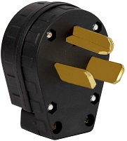
Getting a 240V connection was relatively easy, as I was lucky in that my home lab runs in my basement. Conveniently enough, it is also near my electric clothes dryer which runs on a 30A 240V circuit, with the older 3-pin NEMA 10-30 socket. This connector provides the two phase connections and a neutral connection, but no ground connection. Normally this lack of ground would be a problem, but in the construction of my house, neutral and ground are bonded together at the main circuit breaker panel, an older but valid configuration. So in theory, ground is actually provided through the same neutral connection. Not ideal, but it will work.
New, safer electrical standards have required that new home construction and newly manufactured electric clothes dryers use a NEMA 14-30 connector, which is a four pin 240V, 30A connector that provide two phases, neutral, and ground. A side effect of this is that dryer cords are a commonly donated item when people move houses but keep their old dryers, or purchase new dryers in old homes, and so forth. Either way I knew I could pick one up one of the old-style 3 pin cords for relatively cheap.
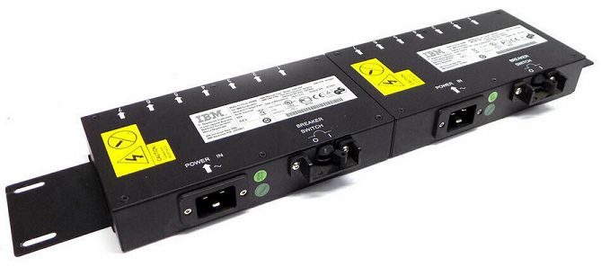
Early on when designing my lab, I decided to stick with IBM and IBM provided equipment, mostly for the challenge and for fun. So as part of my 240V setup, I picked up an IBM Power Distribution Unit, or PDU. I got an “IBM 7109 Intelligent AC PDU 1-EIA Power Distribution Unit” from eBay for about $60. It’s a pretty nice piece of equipment in that it has 1 large “UTG0247” input connection, 12x C14 connections, and has a network connection for power monitoring. Unfortunately it doesn’t provide load switching, but the C14 connections are grouped into pairs with a 15A individual breaker for each pair. It can handle a wide variety of voltages and amperage, but in my case, it can handle up to 32A at 240V. Perfect.
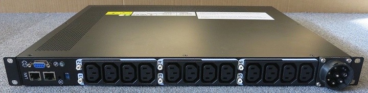
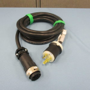
It uses a weird IBM ‘universal’ UTG0247 input cable, which was included in the eBay auction, but can be found relatively cheaply otherwise. It’s a pretty nice 10′ or so, 10AWG cable that terminates in a standard NEMA L6-30P twist-lock connector. The NEMA connector is rated for 240V and 30A so it will again be perfect for the lab. While reading IBM’s documentation, it seems the UTG0247 connector was chosen to allow for various international connections. One standard connector on every PDU, with different cords for each country. Not a bad solution.
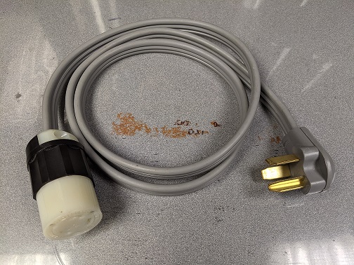
So I created a converter cord to go from the clothes dryer to the PDU cable. A quick trip to the local Habitat for Humanity ReStore go me a great condition but used 3-pin heavy gauge cord for about $5, and a trip to Menards got me the L6-30R connector for about $25. Put two and two together and you got yourself a converter cable.
So to use, I unplug the clothes dryer, plug this in, plug the PDU into this, and plug my equipment into the PDU, and I was running. Kind of annoying, and doesn’t have the best girlfriend-acceptance-factor, but it works and doesn’t require any new circuits to be run. For about $12, I could have cut off the L6-30P plug from the PDU cable and replaced it with a 10-30 plug, but I knew in the back of my mind that using the dryer connection wasn’t a great long-term solution.
So what was a long-term solution? To install a dedicated 30A NEMA L6-30R socket. So I did! For about $30 in parts I added a new circuit and no longer needed to steal the connection from my dryer. However, I did give a lot of thought to the configuration and capacity of my house’s electrical system. Like I mentioned earlier, I have 200A service, so I can’t exceed that with all of my various electrical stuff running all at once. Like most residential electrical service, the main circuit breaker panel is what you would call ‘oversubscribed’. If you add up the total capacity of all of the breakers together, they usually come to a much higher total load, in my case about 415A. If every circuit was running at 100% capacity, this would clearly overload the 200A service and would be tripping breakers all over the place. Now this isn’t a problem because the total sum of all circuits together doesn’t exceed 200A. Each individual circuit is limited to what the breaker allows, and the mains breakers limit the total overall capacity. So by adding up what is a common load, I was able to determine that adding the extra 5A-20A of load of my lab wouldn’t tax the electrical system. There was plenty of ‘overhead’ if you will.
This arrangement has lasted for almost two years. One of the biggest issues with the whole setup was the lack of power control. As I said earlier, running at a normal workload, the entire lab would consume about 1.2KW, and even in ‘standby’ power off mode, about 300W. And since much of my lab work is done intermittently, I didn’t need it on, or even plugged in, all the time. So what I tended to do was before I went to work, pop down to the basement and plug it in. I could then remote into the lab from work and issue power-on commands to things remotely. At the end of the day, then I would shut everything down, and then unplug the lab when I got home. Not a bad solution, but not great either.
I looked into getting a different PDU or some kind of device that would perform power switching. IBM has “Energy Management” PDUs, the 46M4002 or 46M4004 are good examples, and they can do remote power on/off. However, at the time of writing this, even used ones still cost about $100-$200. Kind of high priced for my lab and not really worth the value to me. In theory I could buy an enterprise-grade UPS, as most of them have switching, but 240V versions of those are hard to find, tend to weigh a ton, and can be expensive. Or, in theory, I could build my own device.
So the situation stayed this way for a long time. I actually started down the road of building my own device. I bought a bunch of Allen Bradley buttons, switches, lights, and contactors to build an “Arduino-Controlled Network-Enabled 240V 30A Relay With Manual Override Controls and Power Monitoring”, but I never quite finished it. Then COVID hit and I was at home all the time so the need for power switching pretty much went away! If I needed to power the lab on, I just walked over and did it. Easy peasy.
Then I had a power outage. Only about 2 seconds, but it happened while I was in the middle of doing some AIX VIOS testing. Everything crashed. Hard. Apparently my disk array doesn’t like to be interrupted during array expansion. Luckily I got everything back, but it made me to look into a UPS. But boy, UPS systems are expensive! I had worked some numbers, and to get a UPS with enough capacity to run the lab, voltage and amperage that is, would cost anywhere from a few hundred to thousands of dollars. Yikes! Like I like to say, I didn’t have a ‘Hundreds of Dollars’ problem. It was just a lab, I could work around this issue.
But, as luck would have it, I won an auction for an IBM-branded APC SURT6000, 240V, 30A UPS! The auction branded it as a part for an IBM XIV storage array, and didn’t give much else as far as descriptions. Just a few pictures and an IBM part number. Well, doing some research told me this particular unit would work great for my purposes. It had plenty of capacity, was relatively modern, was network controllable and monitor-able, could do remote power management by turning the UPS load on and off, and based on the pictures it appeared that the batteries still held some charge, so I pulled the trigger. I cost me about $200, $99 for the UPS, and $101 to ship! An early Christmas gift to myself.
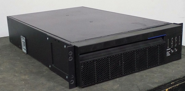
After a very entertaining adventure in getting a 120lb UPS shipped via UPS freight to my house, and then into my basement, I was then ready to start integrating it into my setup.
One of the first things I had to do was make sure it actually worked. The typical way very large APC UPSes are configured is that they don’t have normal input power cords, they are expected to be either hard wired into the building electrical supply, or to have a power whip attached by an electrician. In my case, it appeared that when IBM got these units made, they had an NEMA L6-30P connected to the input. So, it was an easy matter to dig out my old converter cord and plug it into my clothes dryer socket. And when I hit the power on button I got…nothing!
Damn, it was dead. Well, not really, more than likely the batteries were just very low. When I moved it to my basement, I had removed the dual battery packs, but hadn’t done any tests on them. These packs together are called the APCRBC140, with each pack providing 96V DC via 8x 12V 5A SLA batteries in series, with then both packs in series with each other, all together providing 192VDC. When I put my voltmeter on each pack, they were reading at about 60V, or about 7.5V per battery. Not great, but not necessarily a death sentence either. So I popped open the packs and put individual battery chargers on each of the 12V batteries and, thankfully they all took a charge and I was able to bring the packs up to about 80V each.
Then, after putting both packs back into the UPS, I hit the power button and it came to life! I let it charge the batteries overnight, and they all came back without issue! Huzzah!
Other setup tasks I did were configuring the APC SmartSlot network card. Which was very annoying because you have to craft a very special DHCP option 43 configuration for it to pull an DHCP IP after being reset. But once I got that done, I was able to update the firmware of the card, and that was that. I did the basic configuration of the card for my network and it’s worked great since.
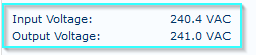
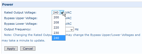
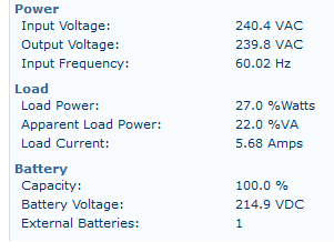
Something else that I did was to be sure to adjust the output voltage of the UPS to be 240V, and not the ‘stock’ 208V. The SURT6000 can support anywhere from 200-240V, and clearly it was originally configured for 208. Adjusting the voltage was as simple as choosing the right voltage in a dropdown list.
Once configured, I did some load testing and eventually deemed it fit for service and mounted it in my lab rack. Now, the problem was that I couldn’t use my original PDU. That PDU needed either that funky UTG connector, or a NEMA L6 connector, neither of which this UPS provided as an output. However, what it did provide was a selection of 8x C14 and 2x C20 connections.
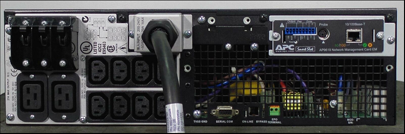
So what I chose to do was put my old 7109 PDU out to pasture and procure a pair of smaller IBM 9306 PDUs. These PDUs take a C20 connection and turn it into 7x C14 connections. By hooking these two PDUs up to the UPS using a C19 to C20 cable, I then effectively got an ‘A’ and ‘B’ side power! So every system that I attach to the UPS that has dual power supplies (which is almost all of them) gets one connection to the ‘A’ PDU, and one to the ‘B’ PDU, mimicking what happens in most data centers with redundant power systems.
So how do I like it now?
It’s great. I now have a much cleaner power connection setup. I have network control and monitoring of my lab. I have a few minutes of runtime for battery backup, and I did it all for less than a few hundred bucks. Can’t complain. It would be nice to have control over the various circuits on the back of the UPS, to, for example, only turn certain things on and off, but in reality that’s not that big of a deal. Also when I shut down the system entirely via the UPS, the ‘standby’ current of the UPS is higher than I would expect, around 60-80W, so I find myself unplugging the UPS if I don’t anticipate using the lab for a few days.
I only have a few things I need to complete to call the project done. Getting a better/appropriate set of rails for the UPS would be nice. They are available but annoyingly expensive for pieces of stamped sheet metal. I also need to get a more permanent power connection for the UPS. I don’t want to keep using the converter cord as it is very inconvenient. I also need to look into what it will take to eventually replace the batteries. They will no doubt be horrifically expensive, so perhaps I can do something DIY when it comes to that time.